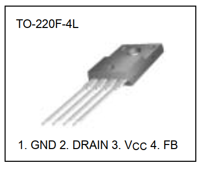
- 5L0380 5L0380 pin description

Pin 1: GND
Pin 2: Drain – this is also same Drain pin of Mosfet inside 5L0380R
Pin 3: Vcc – this Vcc in input VDC max 30VDC , usually VCC is 12VDC
Pin 4: FB – This pin for feedback voltage from output and to stable output voltage.
- 5L0380 5L0380 Absolute Maximum Ratings

- 5L0380 5L0380R work in a real pulse power supply circuit


As you can see in this diagram, from 220V input AC voltage goes through Bridge rectifier to 300VDC, you can flat this 300VDC voltage by some capacitors.
Let’s look at primary coil 1,2 , 300vdc goes through 300K 2W resistor and connects to point 1, the point 2 connects to GND ( GND of primary coil side ) . Let’s look at primary coil 1,2 , 300vdc goes through 300K 2W resistor and connects to point 1, the point 2 connects to GND ( GND of primary coil side ) . then first 300vdc goes through 1,2 coil, it creates induction current in the 1,2 coil, this current is converted to 12VDC and supply power to 5L0380R IC.
The 300VDC line also connects to 3,4 primary coil of pulse transformer, when the 5L0380R is powered, the mosfet inside 5L0380R works and it switches the 300VDC line on and off at a certain frequency, this creates induction currents on secondary coils side. The induction current on 5,6 coil is converted to 5VDC, and the same as 7,8 coil converted to 12VDC. In this circuit two GND points are different. The GND primary coil side and the GND secondary coil side. they are isolated each other for safety. To stable output voltages 5VDC 12VDC it has a voltage feedback block, in this diagram I dont show you , so you can see in details at this article.
feedback voltage signal from PC817 opto goes to pin 4 of 5L0380R, so 5L0380 IC can adjust mosfet switching frequency to stable output voltages 5VDC 12VDC.